Find Electrical Faults Fast With a Circuit Tester
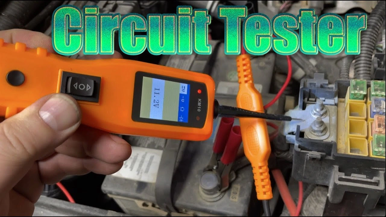
A basic test light ($5-15) checks for power presence by lighting up when touched to a hot wire with the clip grounded. For actual voltage readings, use a digital multimeter ($20-50) set to DC volts. To test a circuit: connect black probe to ground, red probe to the wire being tested. A 12V system should read 12.4-12.6V at the battery, 13.5-14.5V with engine running. No reading means an open circuit; low reading indicates resistance or a bad ground.
Types of Automotive Circuit Testers
Different tools suit different diagnostic needs.
Simple Test Lights
Basic bulb-type testers:
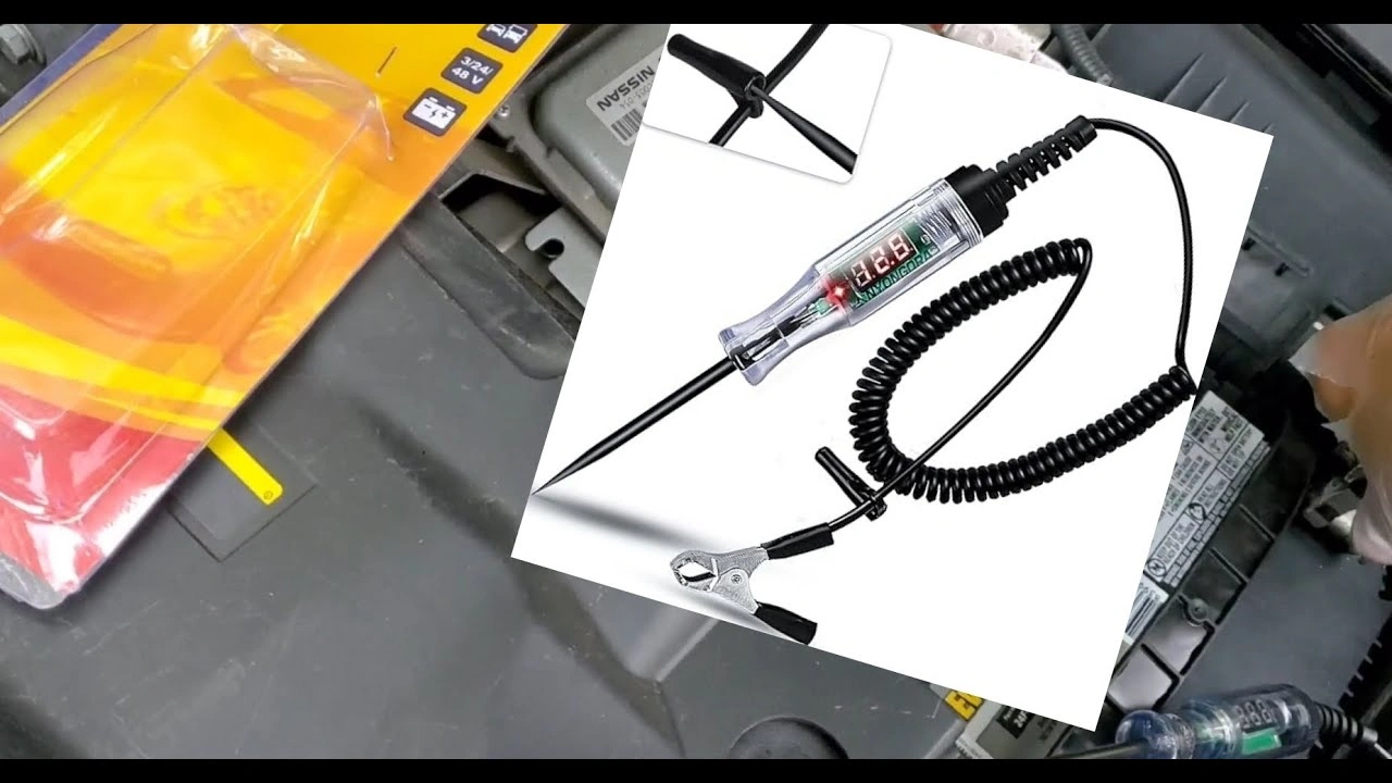
- 12V test light: Shows presence of power
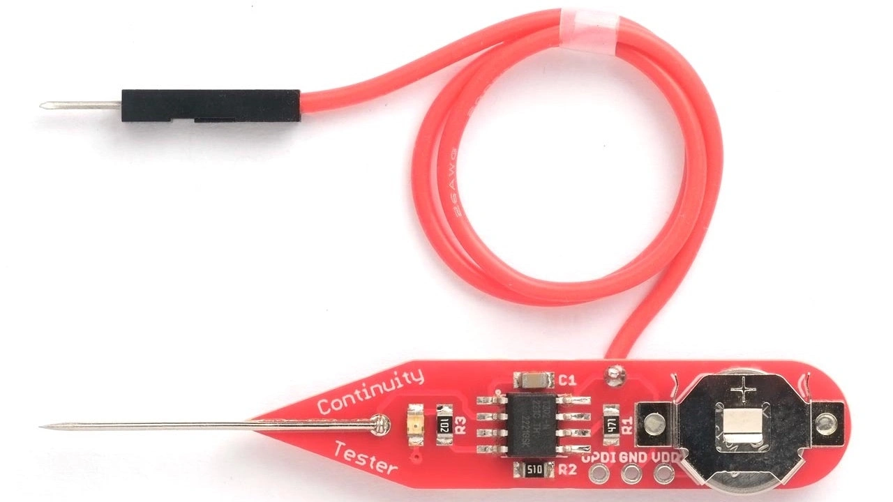
- Self-powered continuity tester: Tests circuits without external power
- Logic probe: For computer circuits (not common in small engines)
Best for: Quick power checks, ground verification, basic troubleshooting
Digital Multimeters
Versatile electronic testers measuring:
- DC voltage: Battery and charging system
- AC voltage: Alternator output (some)
- Resistance (ohms): Component testing
- Continuity: Wire and connection checks
- Current (amps): Draw testing
Best for: Detailed diagnostics, specification testing, professional work
Specialized Testers
Purpose-built diagnostic tools:
- Battery analyzers: CCA and health testing
- Charging system testers: Alternator and regulator
- Ignition testers: Spark and timing
- Fuel injector testers: Pulse and resistance
How to Use a Circuit Test Light
Simple test lights answer basic questions quickly.
Power Testing
To check for 12V power:
- Connect test light ground clip to known good ground
- Touch probe to wire or terminal being tested
- Light illuminates = power present
- No light = no power (or bad ground connection)
Ground Testing
To verify ground circuits:
- Connect test light to battery positive
- Touch probe to suspected ground point
- Light illuminates = good ground
- No light = bad ground connection
Continuity Testing (Self-Powered)
To check wire continuity:
- Disconnect circuit from power
- Connect tester to one end of wire
- Touch other end with probe
- Beep or light = continuous
- Nothing = open circuit
Test Light Limitations
Simple test lights don’t show:
- Actual voltage level
- Resistance values
- Intermittent problems
- Voltage drops under load
Using a Multimeter for Circuit Testing
Digital multimeters provide detailed information.
Setting Up the Meter
- Select correct function (V, Ω, A)
- Choose range (auto-ranging meters do this automatically)
- Connect leads properly (red to positive, black to common)
- Zero the meter if needed for resistance
DC Voltage Measurement
For batteries and 12V circuits:
| Test Point | Expected Reading |
|---|---|
| Fully charged battery | 12.6-12.8V |
| Running (charging) | 13.5-14.5V |
| Accessory circuit on | 12V+ |
| Dead circuit | 0V |
Resistance Measurement
For components and continuity:
| Component | Typical Resistance |
|---|---|
| Good wire | 0-2 ohms |
| Ignition coil primary | 0.5-2 ohms |
| Starter solenoid coil | 2-5 ohms |
| Safety switch (closed) | 0 ohms |
| Open circuit | OL (overload) |
Current Measurement
For draw testing:
- Set meter to amps (A) setting
- Connect in series with circuit
- Measure current flow
- Compare to specifications
Caution: High current can blow meter fuses. Use appropriate range.
Circuit Tests for Small Engine Electrical Systems
Specific tests for typical problems.
Battery Voltage Test
- Set meter to DC volts
- Connect red to positive terminal
- Connect black to negative terminal
- Read voltage
| Voltage | Battery Condition |
|---|---|
| 12.6V+ | Fully charged |
| 12.4V | 75% charged |
| 12.2V | 50% charged |
| 12.0V | 25% charged |
| Below 12V | Discharged/bad |
Charging System Test
- Start engine and let idle
- Measure voltage at battery terminals
- Should read 13.5-14.5V
- Rev engine - voltage should stay steady
| Reading | Indicates |
|---|---|
| 13.5-14.5V | Normal charging |
| Below 13V | Undercharging |
| Above 15V | Overcharging |
| Same as battery | No charging |
Starter Draw Test
Requires amp clamp or high-amp meter:
- Connect amp meter in series with battery cable
- Disable ignition (prevent starting)
- Crank engine and note amp draw
- Compare to specifications
Typical starter draws:
- Small engines: 80-150 amps
- Riding mowers: 100-200 amps
- Large tractors: 150-250 amps
Ignition Coil Test
Primary resistance:
- Disconnect coil wires
- Set meter to ohms
- Measure across primary terminals
- Should read 0.5-2 ohms typically
Secondary resistance (if accessible):
- Measure from primary to spark plug wire terminal
- Should read 5,000-15,000 ohms typically
- Check service manual for exact specs
Safety Switch Testing
For seat switches, blade engagement, brake switches:
- Disconnect switch connector
- Set meter to continuity/ohms
- Test across switch terminals
- Actuate switch - should toggle between open and closed
- Intermittent readings indicate bad switch
Electrical Troubleshooting by Symptom
Use circuit testers to diagnose common problems.
No Crank, No Click
Check in order:
- Battery voltage - Should be 12.4V+
- Battery cables - Voltage at starter terminal should equal battery
- Safety switches - Test each for continuity when actuated
- Ignition switch - Verify power output in start position
- Starter solenoid - Check for power at trigger wire
Clicks But Won’t Crank
- Battery under load - Voltage shouldn’t drop below 10V while cranking
- Cable voltage drop - Less than 0.5V drop across each cable
- Starter draw - Excessive draw indicates bad starter
- Ground circuit - Check engine-to-frame ground
Cranks But Won’t Start
Electrical checks:
- Spark test - Use spark tester, not circuit tester
- Fuel solenoid - Check for 12V when key on
- Ignition module power - Verify supply voltage
- Kill circuit - Ensure not grounded when running
Starts But Dies
- Charging system - Verify charging at idle
- Safety switch intermittent - Wiggle while monitoring
- Ignition power - Check for dropout while running
- Ground connections - Test under vibration
Electrical Accessories Don’t Work
- Fuse continuity - Should have 0 ohms
- Power at component - 12V present?
- Ground at component - Good connection?
- Switch operation - Continuity when on?
- Wire continuity - Check for opens or shorts
Advanced Circuit Testing Techniques
Beyond basic testing.
Voltage Drop Testing
Finds resistance in circuits under load:
- Connect meter across connection being tested
- Operate circuit (draw current through it)
- Measure voltage difference
- Should be less than 0.2V for connections, 0.5V for cables
Parasitic Draw Testing
Finds current drain when equipment off:
- Disconnect battery negative
- Connect amp meter between cable and terminal
- Wait for computers to sleep (1-2 minutes)
- Should read under 50mA for most small engines
- Higher draw indicates parasitic drain
Pull fuses one at a time to isolate circuit with draw.
Intermittent Fault Finding
For problems that come and go:
- Connect meter to suspect circuit
- Monitor while wiggling wires and connectors
- Watch for voltage changes or continuity breaks
- Heat/cool components if temperature related
Circuit Tester FAQ
What’s the best circuit tester for beginners?
Start with a simple 12V test light ($5-10) for power and ground checks. Add a basic digital multimeter ($20-40) for voltage and resistance readings. These handle 90% of small engine diagnostics.
Can I damage electronics with a test light?
Traditional incandescent test lights draw current and can damage some modern computer circuits. For computer-controlled equipment, use a digital multimeter or LED test light that draws minimal current.
Why does my meter show voltage but the circuit doesn’t work?
Probably a ground problem. A circuit needs both power AND ground to function. Test ground path separately. Also, voltage present doesn’t mean adequate current - there may be high resistance limiting power.
How do I know if my multimeter is accurate?
Test a known good battery - it should read 12.6V when fully charged. Check continuity by touching probes together - should read 0 ohms. Replace batteries if readings seem off.
What causes false continuity readings?
Parallel circuits can show continuity through other paths. Always disconnect the component being tested from the rest of the circuit for accurate continuity testing.
Related Guides
- Trailer Wiring Diagrams - Testing trailer light circuits
- Battery Tester Guide - Load testing batteries
- 12V Battery Analyzer - Digital battery diagnostics
- Automotive Wiring Harness Repair - Fixing damaged wiring
- Rechargeable Work Light Guide - LED lighting for repairs
Circuit Tester Summary
A basic test light and multimeter handle most small engine electrical diagnosis. Start with simple tests - battery voltage, power presence, ground integrity - before moving to complex diagnostics. Most electrical problems come down to no power, no ground or high resistance in connections. Systematic testing finds the fault faster than random parts replacement.