Trailer Wiring Diagrams: 4, 5, 6 and 7-Pin Guide
Trailer wiring diagrams for 4-pin, 5-pin, 6-pin and 7-pin connectors. RV blade, round and flat plug pinouts.
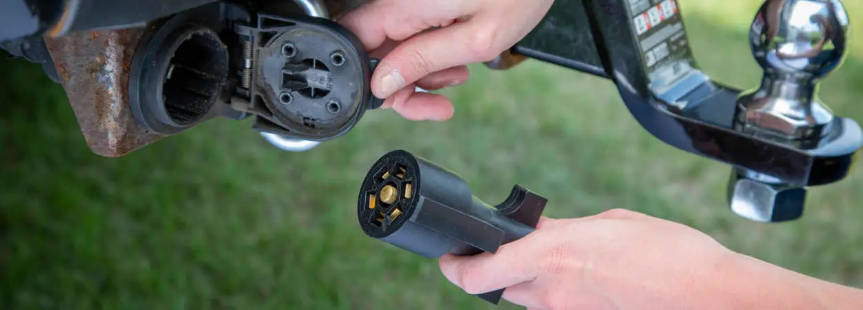
Hooking up trailer lights shouldn’t take all afternoon. But if you’re staring at a bundle of colored wires with no idea what goes where, that’s exactly what happens.
This guide covers the four main trailer connector types: 4-pin, 5-pin, 6-pin and 7-pin. Each section includes a trailer plug diagram showing wire colors, pin positions and what each circuit does. Print this out, keep it in your truck and never guess at wiring for trailer lights again.
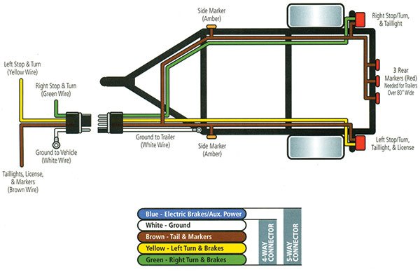
Quick Reference: Trailer Wire Color Codes
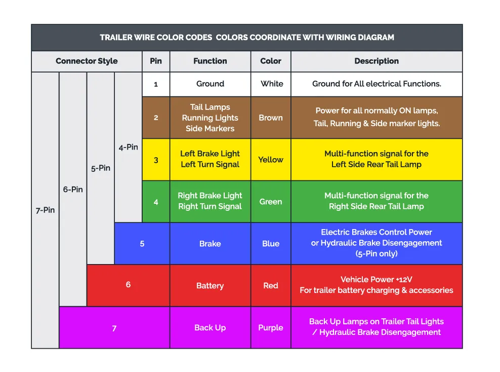
Before getting into specific connectors, here’s the standard color coding used by most trailer manufacturers:
| Wire Color | Function |
|---|---|
| White | Ground |
| Brown | Running lights (tail, marker, license) |
| Yellow | Left turn signal / Left brake light |
| Green | Right turn signal / Right brake light |
| Blue | Electric trailer brakes |
| Red or Black | 12V auxiliary power (battery charge) |
| Purple or Orange | Reverse lights |
These colors follow SAE J1128 standards but not every manufacturer sticks to them. Asian imports and older trailers sometimes use different schemes. When in doubt, use a multimeter or circuit tester to test each wire.
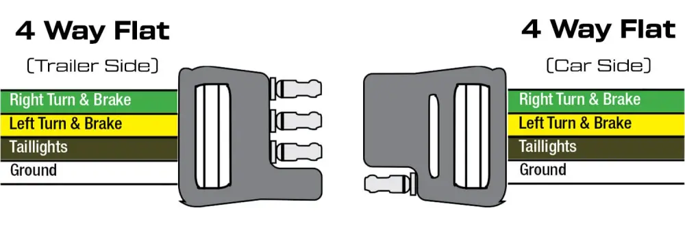
4-Pin Trailer Wiring Diagram
The 4-pin flat connector is the most common trailer plug in North America. You’ll find it on utility trailers, small boat trailers, cargo haulers and lawn equipment trailers. It handles basic lighting — ground, running lights, left turn and right turn. Need brakes or aux power? Check our 5-pin, 6-pin or 7-pin guides.
What Each Pin Does
| Pin | Wire Color | Function |
|---|---|---|
| 1 | White | Ground |
| 2 | Brown | Running lights |
| 3 | Yellow | Left turn / Brake |
| 4 | Green | Right turn / Brake |
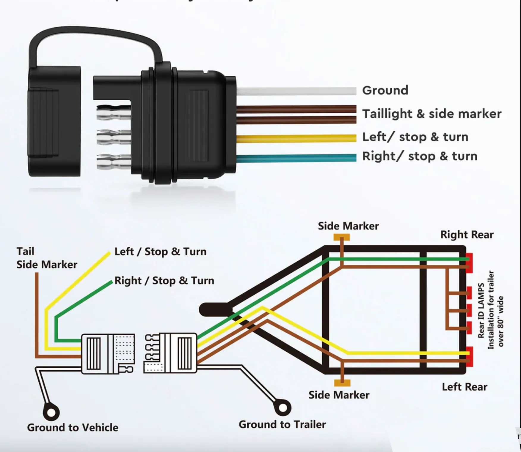
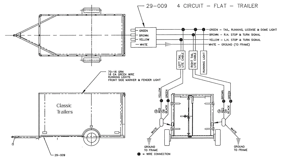
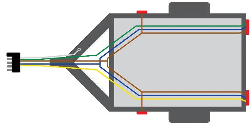
This pinout works for utility trailers and basic boat trailers. The diagram below shows the same layout in schematic form.
Wiring Notes
The 4-pin setup uses combined brake and turn signal circuits. When you hit the brakes, both yellow and green wires get power. When you signal left, only the yellow wire flashes. This works because most trailer lights use dual-filament bulbs or LEDs that can handle both functions.
Ground is critical. The white wire must make solid contact with bare metal on both the trailer frame and tow vehicle. A bad ground causes dim lights, flickering or no lights at all. If your lights act weird, check ground first with a voltage tester.
Troubleshooting 4-Pin Connections
Lights work on one side only: Check the ground on the dead side. Trailer frames can corrode where the light mounts, breaking the ground path. Run a dedicated ground wire from each light to the connector.
Running lights work but turn signals don’t: The tow vehicle’s turn signal circuit might be overloaded. This happens when towing with a car that wasn’t designed for trailers. Install a trailer wiring converter or relay pack.
All lights dim when brakes are applied: Ground problem. Current is finding a path back through the running light circuit instead of the ground wire.
If you need to rewire a trailer from scratch, the Oyviny 4-way flat trailer wiring harness comes in a 22ft length with nylon tube protection.
5-Pin Trailer Wiring Diagram
The 5-pin connector adds one circuit to the basic 4-pin setup. That extra wire is typically for electric brakes or a separate brake light circuit.
What Each Pin Does
| Pin | Wire Color | Function |
|---|---|---|
| 1 | White | Ground |
| 2 | Brown | Running lights |
| 3 | Yellow | Left turn |
| 4 | Green | Right turn |
| 5 | Blue | Electric brakes or separate brake lights |
When You Need 5-Pin
Most people use 5-pin when they have a trailer with electric brakes but don’t need auxiliary power or reverse lights. It’s less common than 4-pin or 7-pin because it sits in an awkward middle ground. If you’re installing new wiring and think you might need brakes later, just go with 7-pin. For detailed 5-pin installation steps, check out our 5-pin trailer connector wiring guide.
The blue wire connects to a brake controller mounted in the tow vehicle. When you press the brake pedal, the controller sends voltage to the trailer brakes. More pedal pressure means more voltage, which means harder trailer braking.
6-Pin Trailer Wiring Diagram
Six-pin connectors are common on gooseneck trailers, horse trailers and some RV setups. Compared to 4-pin, you get two extra circuits: electric brakes and auxiliary power.
Pinout
| Pin | Wire Color | Function |
|---|---|---|
| 1 | White | Ground |
| 2 | Brown | Running lights |
| 3 | Yellow | Left turn / Brake |
| 4 | Green | Right turn / Brake |
| 5 | Blue | Electric trailer brakes |
| 6 | Red or Black | 12V auxiliary power |
Wiring Notes
The 12V auxiliary circuit typically runs straight to the trailer battery or interior lights. This wire can carry significant current so make sure it’s fused at the tow vehicle. A short in this circuit can drain your truck battery overnight or worse.
Some 6-pin setups use the sixth wire for reverse lights instead of aux power. Check the trailer documentation or test with a multimeter before connecting. Our 6-pin trailer connector guide covers gooseneck and horse trailer wiring in detail.
If your truck has a 7-pin socket but your trailer uses 6-pin round, the Nilight 7-to-6 pin adapter converts between the two styles without rewiring.
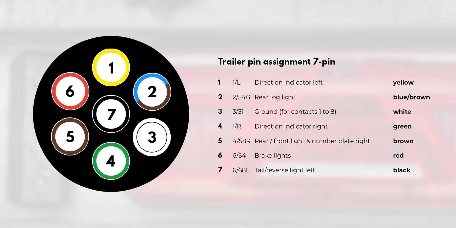
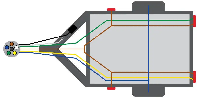
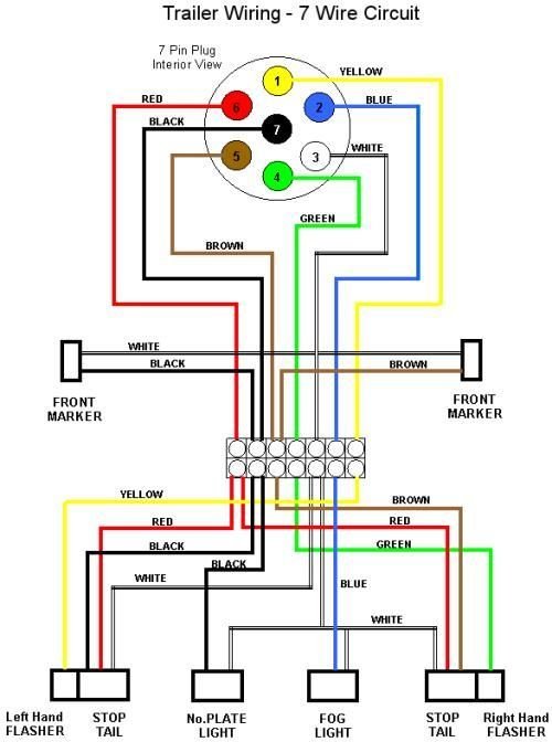
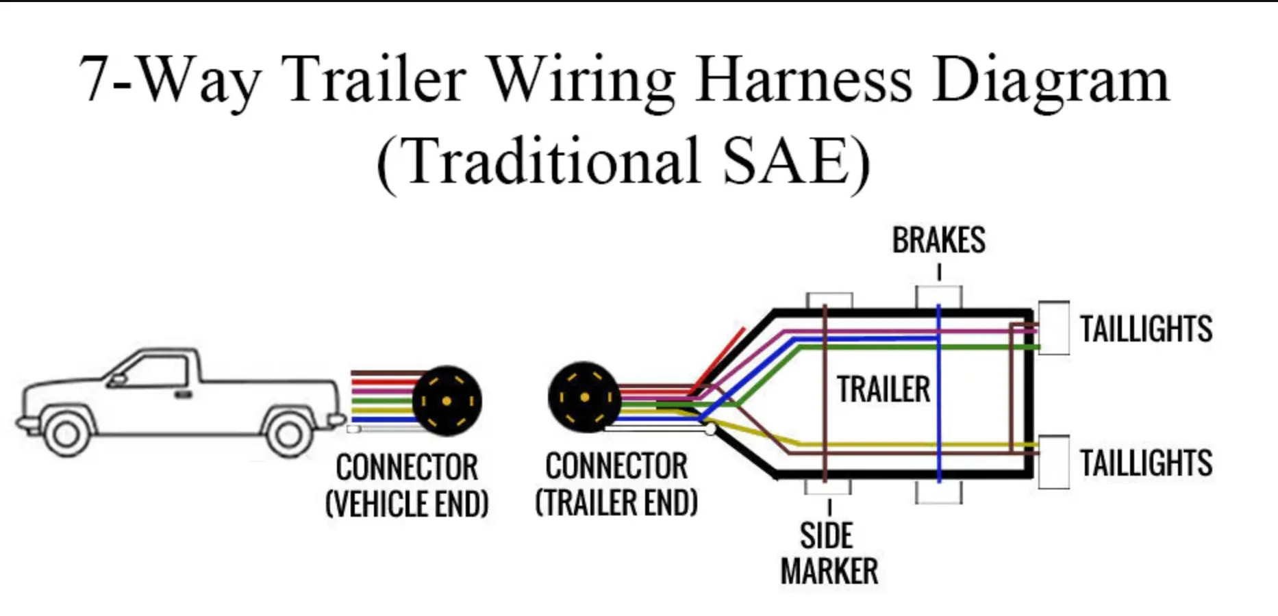
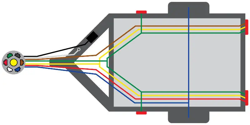
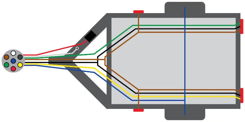
7-Pin Trailer Wiring Diagram
The 7-pin RV blade connector handles everything: lights, brakes, aux power and reverse lights. It’s the standard for travel trailers, campers, large boat trailers and enclosed cargo trailers. Our 7-pin trailer connector guide covers equipment trailer specifics in more detail.
What Each Pin Does
| Pin Position | Wire Color | Function |
|---|---|---|
| Center | White | Ground |
| 6 o’clock | Brown | Running lights |
| 9 o’clock | Yellow | Left turn / Brake |
| 3 o’clock | Green | Right turn / Brake |
| 12 o’clock | Blue | Electric brakes |
| 8 o’clock | Red or Black | 12V auxiliary power |
| 4 o’clock | Purple or Orange | Reverse lights |
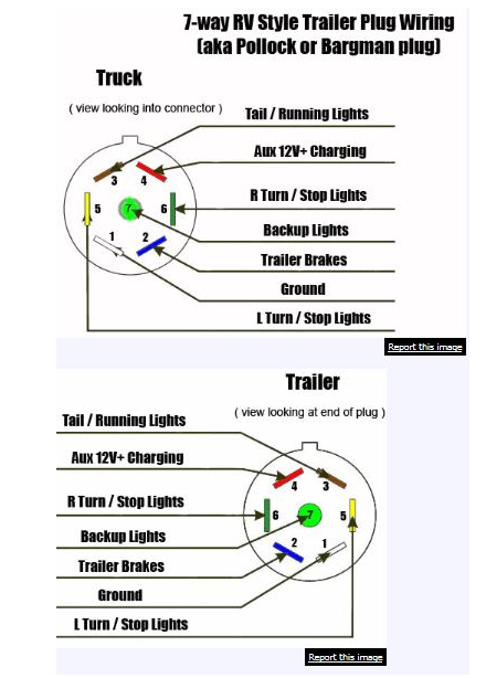
7-Pin Connector Types
There are two main 7-pin designs and they’re not interchangeable:
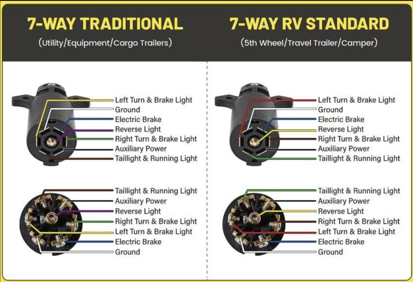
RV Blade (flat pins): The most common seven way trailer plug type. Used on pickup trucks, SUVs and most travel trailers sold in North America. Pins are flat metal blades arranged in a circle.
Round pins: Less common in the US but still found on some commercial and imported trailers. This seven pin round connector uses round pins instead of flat blades. The pinout can differ from RV blade so verify before connecting.
Vehicle Side Wiring
The tow vehicle side has female sockets instead of male pins but follows the same layout. Most trucks with factory tow packages come pre-wired in the bumper or hitch receiver.
If your truck only has a 4-pin factory connector, you’ll need a wiring harness to add the extra circuits. Use an automotive circuit tester to identify existing wires before splicing. This involves tapping into the brake controller circuit, reverse light wire and running a fused 12V line from the battery.
Wiring a 7-Pin Plug From Scratch
Here’s the process if you’re installing a new 7-pin connector:
-
Run your wires. Use a 7-conductor trailer cable from the hitch area to your trailer tongue. Leave extra length for turns. The Nilight 7-way trailer extension cord is a solid choice with heavy-duty copper terminals.
-
Strip and tin the ends. Strip about 3/8” of insulation and apply solder to prevent fraying.
-
Connect ground first. The white wire goes to the center pin. On the trailer side, bolt it directly to the frame with a star washer.
-
Connect each circuit. Follow the pinout diagram. Use dielectric grease inside the connector to prevent corrosion.
-
Test before you tow. Have someone watch the trailer while you test each function: running lights, left turn, right turn, brakes and reverse.
Converting Between Connector Types
Sometimes the trailer has a different connector than your tow vehicle. Here’s what works and what doesn’t.
4-Pin to 7-Pin Adapters
A 4-pin to 7-pin adapter lets you plug a 4-pin trailer into a 7-pin vehicle socket. The adapter passes through the four basic circuits (ground, running, left, right) and leaves the other three pins unconnected.
This works fine because you’re only using circuits that exist on both ends. The trailer doesn’t have electric brakes or aux power so it doesn’t need those wires.
The Seamaka 4-Pin to 7-Pin Trailer Adapter is a solid budget option with a mounting bracket and dual outputs.
7-Pin to 4-Pin Adapters
Going the other direction is trickier. A 7-pin to 4-pin adapter plugs into your trailer’s 7-pin connector and provides a 4-pin plug for the vehicle.
This only works for basic lighting. You lose electric brakes, aux power and reverse lights because the 4-pin vehicle socket doesn’t have those circuits. If your trailer has electric brakes, this adapter makes them non-functional—dangerous on a heavy trailer.
When Adapters Won’t Work
If you need electric brakes or aux power, adapters aren’t the answer. You need to add those circuits to the tow vehicle:
- Electric brakes: Install a brake controller and run a wire to the trailer connector
- Aux power: Run a fused 12V line from the battery to the trailer connector
- Reverse lights: Tap into the vehicle’s reverse light circuit
Common Problems and Fixes
Most trailer wiring issues fall into a few categories. Here’s how to diagnose and fix them.
No Lights at All
Start at the vehicle. Plug in the trailer connector and check for voltage at each pin with a multimeter. Set the meter to DC volts, touch the black probe to a good ground and test each pin while activating that circuit. A 12V battery analyzer can verify your tow vehicle’s electrical system is supplying proper voltage. If you’re dealing with trailer batteries, see our guide on wiring batteries in series vs parallel.
If you get voltage at the vehicle connector but no lights on the trailer, the problem is on the trailer side. Check the ground connection at the trailer frame and inspect the wiring for damage.
If you don’t get voltage at the vehicle connector, check the fuses. Many trucks have separate fuses for trailer lighting. Also verify the wiring harness connector behind the bumper is plugged in—they can vibrate loose.
Lights Work Intermittently
Nine times out of ten this is a ground issue. Trailer grounds corrode over time, especially on boat trailers that get dunked in water. The connection works when everything is cool and dry but fails when it heats up or gets wet.
Fix it by running dedicated ground wires from each light fixture back to the main connector. Don’t rely on the trailer frame as a ground path.
Turn Signals Flash Fast on Tow Vehicle
This happens when the trailer lights draw less current than the flasher expects. LED trailer lights are the usual culprit—they use so little power that the flasher thinks a bulb is burned out.
Fix it by installing a load resistor on the trailer or replacing the tow vehicle’s flasher with an LED-compatible unit. The resistor is easier but wastes power as heat. The flasher replacement is cleaner.
Electric Brake Troubleshooting
If brakes lock up, the brake controller gain is set too high or there’s a short in the blue wire. Reduce the gain setting and check for bare wire contacting the frame.
If brakes don’t work at all, verify the blue wire has voltage when you press the brake pedal. If it does, the problem is in the trailer brake magnets or wiring. If it doesn’t, check the brake controller and its connection to the vehicle’s brake switch.
How to Wire a 5-Pin Relay
Adding auxiliary circuits often requires a relay. A 5-pin relay lets you control high-current loads (like brake controllers or aux lighting) from a low-current switch.
5-Pin Relay Pinout
| Pin | Label | Function |
|---|---|---|
| 85 | Coil (-) | Ground for relay coil |
| 86 | Coil (+) | 12V trigger from switch |
| 30 | Common | Power input from battery |
| 87 | Normally Open | Output when relay is ON |
| 87a | Normally Closed | Output when relay is OFF |
Wiring a 5 Pin Relay Step by Step
- Connect pin 30 to your 12V power source through an inline fuse
- Connect pin 85 to a good chassis ground
- Connect pin 86 to your trigger source (switch, brake signal, ignition)
- Connect pin 87 to your load (lights, brake controller, accessory)
- Leave pin 87a disconnected unless you need a normally-closed circuit
Common uses in trailer setups include automatic brake light activation, auxiliary battery charging circuits and switched accessory power for trailer jacks or winches. The irhapsody 5-pin relay kit includes waterproof housings and pre-wired pigtails for easy installation.
Commercial and Semi Trailer Wiring
Commercial rigs use the same 7-pin concepts but with heavier-gauge wire and weatherproof connectors. The pinout follows the standard 7-way layout — the difference is connector durability and wire capacity.
SAE J560 connectors are standard on semi trucks instead of RV blade. Round pins rated for commercial duty cycles. Use 10-gauge minimum for all circuits.
Best Practices
A few tips from years of trailer repairs:
Use dielectric grease. Fill the connector with dielectric grease before plugging it in. This keeps moisture out and prevents corrosion. Reapply it once a year.
Inspect wiring annually. Look for cracked insulation, worn spots where wires rub on frame edges and corroded connections. Fix small problems before they leave you stranded.
Run wires inside conduit. Exposed trailer wiring takes abuse from road debris and weather. Split loom or wire conduit protects it and makes the installation look professional.
Keep a spare bulb kit. A burned-out brake light will get you pulled over. Keep spare bulbs, fuses and a basic wiring repair kit in the tow vehicle.
Test before every trip. Takes 30 seconds. Have someone watch the trailer while you cycle through running lights, left turn, right turn, brakes and reverse. Way easier than getting a fix-it ticket.
Summary
The color codes stay consistent across 4, 5, 6 and 7-pin setups. White is always ground, brown is running lights, yellow is left and green is right. Extra pins add brakes (blue), aux power (red/black) and reverse (purple/orange).
Related Guides
- Tongue Weight Calculator - Calculate proper trailer tongue weight
- 5-Pin Trailer Connector Wiring - For trailers with surge brakes
- 6-Pin Trailer Connector Guide - Gooseneck and horse trailer wiring
- 7-Pin Trailer Connector Guide - Equipment trailer specifics and installation
- Battery Series and Parallel Wiring - For trailer battery setups
- Automotive Circuit Tester Guide - Testing trailer circuits