Read Voltage Like a Pro: Testing Small Engine Electrical Systems
To use a multimeter for voltage testing, plug the black probe into COM and red into VΩ, then turn the dial to DC voltage (V with straight line) for batteries or AC voltage (V with wavy line) for outlets. Touch red probe to positive/hot and black to negative/neutral—a car battery should read 12.6V DC, a wall outlet reads 120V AC. Digital multimeters cost $15-50 for basic models and $50-150 for automotive-grade units with additional functions.
Types of Testers
Different tools for different needs.
Simple Test Lights
Basic presence testing:
- Bulb illuminates when voltage present
- No numeric reading
- Inexpensive and durable
- Good for quick checks
Best for: Verifying power presence, checking grounds.
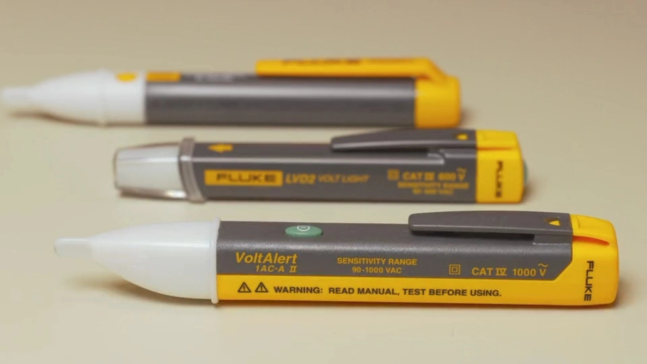
Non-Contact Voltage Testers
Detect voltage without touching wires:
- LED or beep indicates voltage
- Works through insulation
- Very safe for initial checks
- Can have false positives
Best for: Initial safety checks, finding live wires.
Digital Multimeters
Precise voltage measurement:
- Numeric voltage display
- Multiple measurement modes
- Most versatile option
- Essential for diagnosis
Best for: All electrical troubleshooting, specification testing.
Analog Meters
Traditional needle-type:
- Moving needle display
- Can show fluctuations
- Less common now
- Requires more skill to read
Best for: Observing voltage changes, some prefer the visual.
How to Perform Basic Tests
Fundamental techniques.
DC Voltage Measurement
Most small engine circuits are DC:
- Set meter to DC volts (V⎓ or VDC)
- Select appropriate range (20V for 12V systems)
- Connect red probe to positive point
- Connect black probe to ground
- Read voltage on display
Proper Grounding
Good ground connection is essential:
- Connect black probe to clean metal
- Battery negative is ideal reference
- Painted surfaces don’t conduct
- Corroded surfaces give false readings
Polarity
Understanding positive and negative:
- Red probe to higher potential
- Black probe to lower potential
- Reversed shows negative reading
- Doesn’t damage digital meters
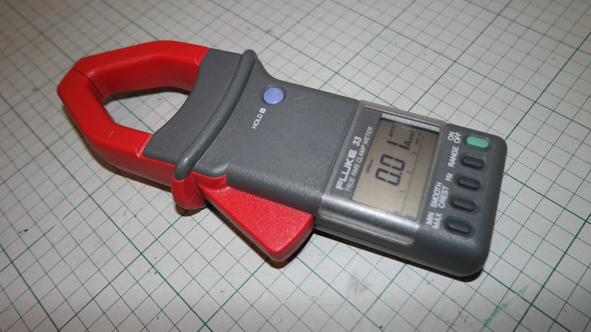
AC Voltage Measurement
Some components produce AC:
- Stator/alternator output
- Set meter to AC volts (V~ or VAC)
- Polarity doesn’t matter for AC
- Used for charging system diagnosis
Common Tests for Small Engines
Specific tests you’ll perform regularly.
Battery Voltage
The starting point for most diagnosis:
| Reading | Condition |
|---|---|
| 12.6V+ | Fully charged |
| 12.4V | 75% charged |
| 12.2V | 50% charged |
| 12.0V | 25% charged |
| Below 12V | Discharged |
Charging System Output
Verify charging while running:
- Connect meter to battery
- Start engine
- Read voltage at idle
- Rev to mid-range
| Reading | Indicates |
|---|---|
| 13.5-14.5V | Normal charging |
| Below 13V | Undercharging |
| Above 15V | Overcharging |
Starter Circuit
Check power reaches starter:
- Measure battery voltage
- Measure voltage at starter terminal
- Should be nearly equal
- Large drop indicates cable/connection problem
Safety Switch Testing
Verify switches receive and pass power:
- Measure voltage input to switch
- Actuate switch
- Measure voltage output
- Should equal input when closed
Ignition System Power
Check ignition components receive power:
- Locate ignition power wire
- Measure with key on
- Should read battery voltage
- No power = check wiring and switches
Reading Your Results
Understanding what voltage means.
Expected Voltages
Common readings in 12V systems:
| Component/Location | Expected Voltage |
|---|---|
| Battery (resting) | 12.6V |
| Battery (charging) | 13.5-14.5V |
| Power circuits (key on) | 12V+ |
| Ground circuits | 0V |
| Switched circuits (off) | 0V |
| Switched circuits (on) | 12V |
Voltage Drop
Resistance causes voltage loss:
- Test across connections under load
- Should be less than 0.2V across good connections
- Higher drop = resistance problem
- Clean or replace connection
Low Voltage Causes
When readings are lower than expected:
- Weak battery
- Corroded connections
- Undersized wiring
- High resistance in circuit
- Excessive loads
No Voltage Causes
When reading is zero:
- Open circuit (broken wire)
- Blown fuse
- Failed switch
- Disconnected connector
- Ground problem (if testing relative to ground)
Troubleshooting Techniques
Systematic diagnosis approach.
Following Power
Trace voltage through circuit:
- Start at battery (should have 12.6V)
- Check at fuse (both sides)
- Check at switch input
- Check at switch output (switch on)
- Check at component
First point with no voltage indicates problem location.
Load Testing
Voltage under load reveals problems:
- Connect meter across suspect connection
- Operate circuit
- Measure voltage drop
- Drop indicates resistance
Helps find intermittent problems that look fine at rest.
Ground Testing
Testing ground circuits:
- Connect red probe to battery positive
- Touch black probe to ground points
- Should read full battery voltage
- Low reading = bad ground
Intermittent Problems
Finding occasional failures:
- Connect meter to suspect circuit
- Monitor while wiggling connections
- Watch for voltage changes
- Operate equipment over bumps
Safety Tips
Staying safe during testing.
Electrical Safety
- Don’t touch live circuits
- Use insulated probes
- Work on dry surfaces
- Disconnect battery for some repairs
Battery Safety
- Batteries produce hydrogen gas
- Keep sparks away
- Wear eye protection
- Handle carefully
Hot Surfaces
- Engines get hot
- Exhaust burns quickly
- Let equipment cool when possible
- Be aware of hot areas
Frequently Asked Questions
What voltage should I see on a good battery?
A fully charged, resting 12V battery reads 12.6-12.8V. Right after charging, it may read slightly higher (surface charge). Below 12.4V indicates the battery needs charging.
Why does my meter show different readings each time?
Possible causes: unstable connection, fluctuating source, meter issue. Ensure solid probe contact. For circuits that should be stable, fluctuation indicates a problem.
Can I damage my meter by testing wrong?
Measuring voltage is generally safe. However, setting meter to amps or resistance mode while connected to a voltage source can damage the meter or blow its internal fuse.
What’s the difference between testing voltage and continuity?
Voltage testing measures electrical pressure in a circuit with power applied. Continuity testing checks if a path exists with power removed. Different tests, both useful.
Do I need an expensive multimeter?
For most small engine work, a basic $20-40 digital multimeter works fine. More expensive meters offer better accuracy, durability and features - worth it for professionals.
Summary
A voltage tester is essential for diagnosing electrical problems. Start with simple tests - battery voltage and charging system output catch most issues. Learn to follow voltage through circuits to isolate problems. A basic multimeter handles nearly all small engine electrical diagnosis.
Related Guides
- Series vs Parallel Battery Wiring - Testing voltage across battery banks
- Trailer Wiring Diagram Guide - Diagnose trailer lighting with a voltage tester
- How to Use a Multimeter - Full multimeter guide for beginners
- Automotive Circuit Tester Guide - Dedicated circuit testing tools
- 12V Battery Analyzer Guide - Automated battery diagnostics
- Alternator Tester Guide - Charging system testing