6-Pin Wiring for Gooseneck and Horse Trailers: Diagram and Colors
The 6-pin trailer connector wiring uses white (ground), brown (running lights), yellow (left turn/brake), green (right turn/brake), blue (electric brakes) and red or black (12V auxiliary power). You’ll find this 6 pin trailer plug on gooseneck trailers, horse trailers and older RV setups. Installation runs about 2 hours DIY. For wiring diagrams of all connector types including 4-pin and 7-pin, see our complete trailer wiring guide.
6-Pin Connector Overview
The 6-pin round connector sits between the basic 4-pin flat and the full-featured 7-pin blade. It handles everything most trailers need: lights, brakes and battery charging.
Where You’ll Find 6-Pin
These connectors show up on:
- Gooseneck trailers (flatbeds, car haulers)
- Horse trailers and livestock trailers
- Older travel trailers and campers
- Heavy utility trailers with brakes
- Some boat trailers with onboard batteries
Why 6-Pin Instead of 7-Pin
Plenty of trailers don’t need reverse lights. The 6-pin gives you electric brakes and aux power without that extra circuit. It’s simpler wiring and works fine for trailers that don’t back up often or have their own backup camera system.
Horse trailer owners stick with 6-pin because it does exactly what they need. Interior lights work. Brakes work. No reason to rewire for a reverse light they’ll never use. Need reverse lights? Check the 7-pin connector guide instead.
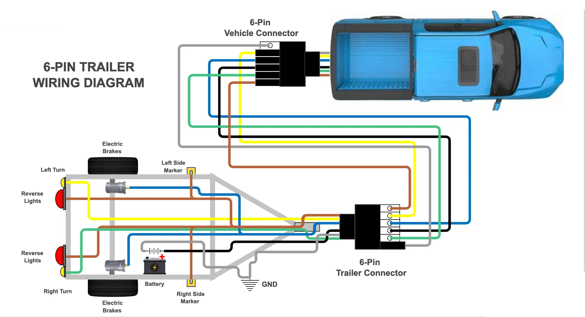
6 Pin Trailer Wiring Diagram
Here’s the standard 6-pin round connector pinout looking at the plug face (what you see when looking at the connector end):
 ○ Brown (Running)

 ○ Yellow ○ Green
 (Left Turn) (Right Turn)

 ○ White (Ground)

 ○ Blue ○ Red/Black
 (Brakes) (12V Aux)
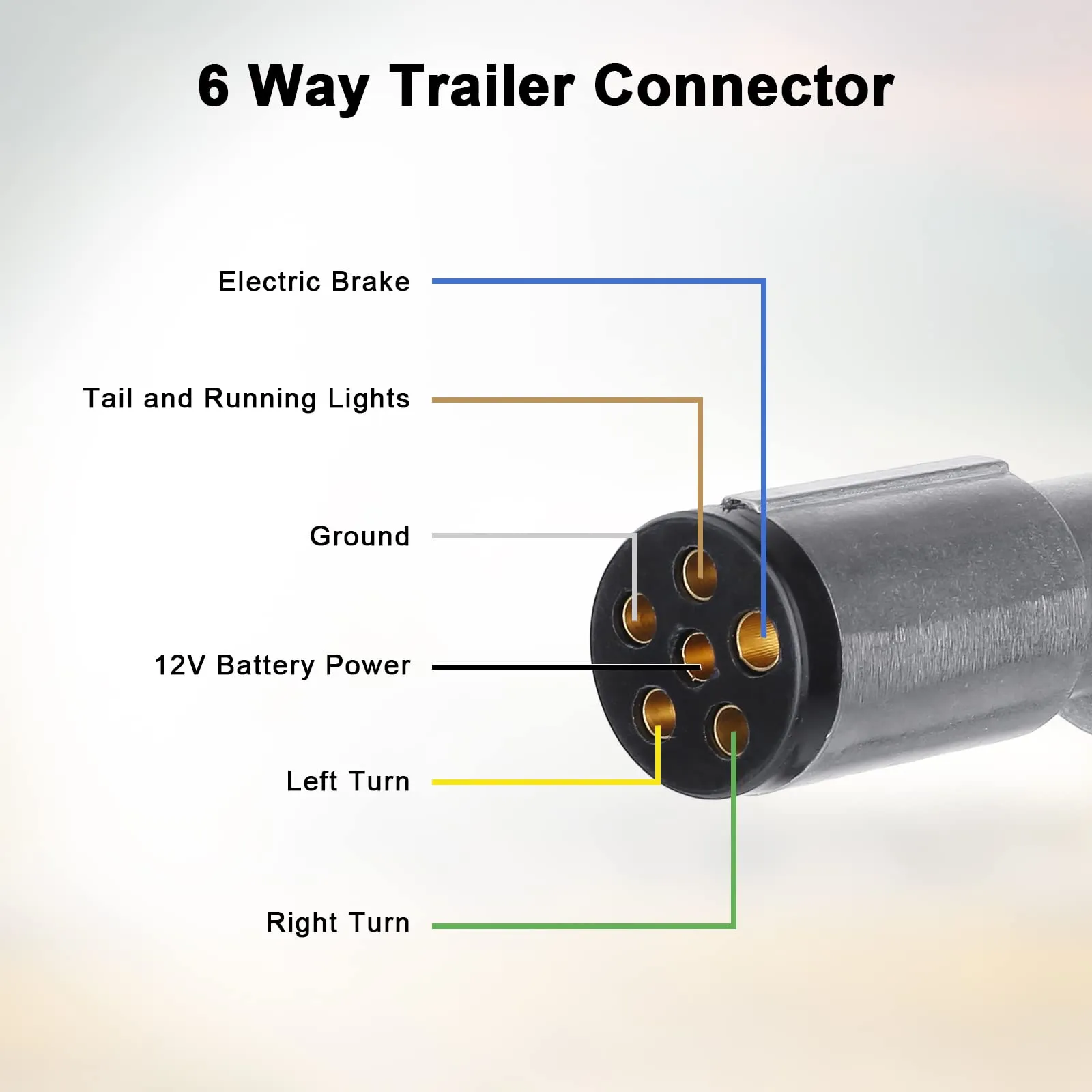
Pin Position Reference
| Position | Wire Color | Function |
|---|---|---|
| 12 o’clock | Brown | Running/tail lights |
| 10 o’clock | Yellow | Left turn and brake |
| 2 o’clock | Green | Right turn and brake |
| 6 o’clock | White | Ground |
| 8 o’clock | Blue | Electric brakes |
| 4 o’clock | Red or Black | 12V auxiliary power |
The positions use clock references because 6-pin round connectors orient the same way every time. Brown at the top, ground at the bottom.
Wiring Colors and Functions
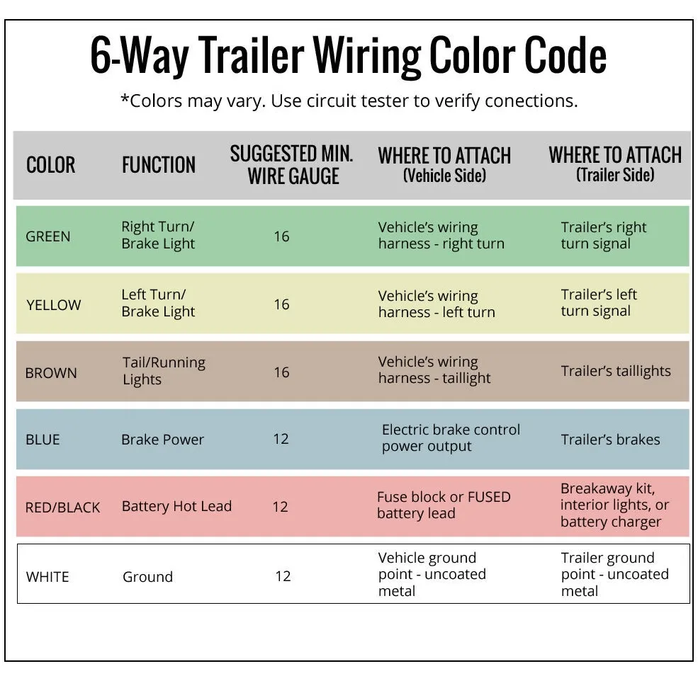
Each wire has one job. Get them right and your trailer lights up correctly every time.
Ground (White)
The foundation of every circuit. White wire runs to clean bare metal on the trailer frame. Bad grounds cause more trailer light problems than anything else. Use a voltage tester to verify your ground connection.
Mount it with a star washer under the bolt head. Scrape paint off the frame first. Hit it with dielectric grease after tightening.
Running Lights (Brown)
Powers all the marker lights, clearance lights and tail lights. These stay on whenever the truck’s headlights or parking lights are on.
Brown wire connects to the taillight circuit in your tow vehicle. It carries relatively low current since LED lights don’t draw much.
Left Turn/Brake (Yellow)
Handles left turn signal and brake light on the left side of the trailer. These share one circuit because the same bulb does both jobs.
When you hit the brakes, both yellow and green wires get power. When you signal left, only yellow flashes.
Right Turn/Brake (Green)
Same deal as yellow but for the right side. Right turn signal and brake light share this wire.
Electric Brakes (Blue)
This one connects to your brake controller. When you press the brake pedal, the controller sends voltage down the blue wire to the trailer brake magnets. Test the circuit with an automotive circuit tester before hitting the road.
More pedal pressure means more voltage means harder braking. The controller modulates this automatically. Without a brake controller installed in your truck, this wire does nothing.
12V Auxiliary (Red or Black)
Provides constant 12V power for charging trailer batteries or running accessories. This wire stays hot when connected, even with the truck off.
Common uses:
- Charging breakaway battery
- Interior trailer lights
- Electric fans or vents
- Water pumps on horse trailers
- Refrigerator power on campers
Fuse this wire. A short in the aux circuit can drain your truck battery overnight or start a fire. Use a 30-amp inline fuse near the truck battery.
How to Install a 6-Pin Trailer Connector
Installing a 6-pin system takes longer than 4-pin but it’s straightforward with the right approach.
Tools You’ll Need
- Wire strippers
- Crimping tool
- Soldering iron (recommended)
- Heat shrink tubing
- Multimeter
- Drill and bits
- Dielectric grease
Vehicle Side Installation
Step 1: Plan your wiring route
Run wires from the engine bay (for aux power) and brake controller location down to the hitch area. Keep wires away from exhaust heat and moving parts.
Step 2: Connect the brake controller
Mount the controller under the dash where you can see the display. Run the blue wire from controller output to the rear connector location.
Step 3: Wire the aux power circuit
Run a heavy gauge wire (10 AWG minimum) from the truck battery to the connector. Install a 30-amp fuse within 18 inches of the battery. This protects against shorts.
Step 4: Tap into lighting circuits
For brown, yellow and green:
- Use a vehicle-specific wiring harness if available (cleanest install)
- Or splice into existing taillight wires with T-taps or solder
Step 5: Establish ground
Bolt the white wire to a clean frame point near the connector. Star washer, bare metal, dielectric grease.
Step 6: Mount the connector
Position it where the trailer plug reaches easily. Secure with bolts or a hitch-mounted bracket. Leave enough wire for connector replacement later.
Trailer Side Installation
Step 1: Plan wire routing
Run wires through the frame tubes or external conduit. Protect them from road debris and moisture.
Step 2: Install the tongue connector
Mount it pointing down or sideways so water doesn’t pool inside. Leave a service loop of wire so the connector can move without stressing connections.
Step 3: Run wires to each light
- Brown to every running light
- Yellow to left side brake/turn lights
- Green to right side brake/turn lights
- White to frame ground points near each light cluster
Step 4: Wire the brake magnets
Blue wire splits to feed both brake assemblies. Use proper gauge wire for the run length. Brake magnets draw significant current.
Step 5: Connect aux power loads
Red/black wire goes to battery charger, fuse panel or directly to accessories. Fuse each branch circuit appropriately.
Step 6: Test everything
Connect to truck. Test each function:
- Running lights (all markers lit)
- Left turn (left side flashes)
- Right turn (right side flashes)
- Brakes (both sides solid)
- Brake controller (hear magnets engage)
- Aux power (voltage at trailer battery or accessory)
Adapters
When your truck and trailer don’t match, adapters bridge the gap.
Common Adapter Scenarios
| Truck Has | Trailer Has | Solution |
|---|---|---|
| 7-pin blade | 6-pin round | 7-to-6 adapter |
| 6-pin round | 7-pin blade | 6-to-7 adapter (limited) |
| 4-pin flat | 6-pin round | 4-to-6 adapter (no brakes/aux) |
| 6-pin round | 4-pin flat | 6-to-4 adapter |
What Adapters Can’t Do
A 4-to-6 adapter gives you lights only. No electric brakes. No aux power. The circuits simply don’t exist in 4-pin.
A 6-to-7 adapter won’t give you reverse lights. The 6-pin doesn’t carry that signal. Everything else works fine.
When to Skip the Adapter
Rewire instead of using adapters when:
- You tow the same trailer frequently
- Adapter connections keep corroding
- You need functions the adapter can’t provide
- Clean appearance matters (shows, sales)
Troubleshooting 6-Pin Problems
Most issues come down to grounds, corrosion or damaged wires. Work through these systematically.
Nothing Works At All
- Check truck fuse for trailer circuit
- Verify connector is fully seated
- Test for 12V at truck connector pins
- Check ground at both truck and trailer
Lights Work But No Brakes
Electric brake issues when lights function:
- Brake controller getting power?
- Controller showing trailer connected?
- Blue wire has continuity to trailer?
- Breakaway switch in run position?
- Test brake magnet resistance (should be 3-4 ohms each)
No Aux Power
The 12V auxiliary circuit troubleshooting:
- Check inline fuse near truck battery
- Test for voltage at truck connector
- Verify red/black wire continuity
- Check trailer side fuse or breaker
One Side Doesn’t Work
Left or right side out:
- Check bulbs on that side
- Test ground at that light cluster
- Check wire continuity from connector to lights
- Look for pinched or cut wires
Intermittent Problems
Connections that work sometimes:
- Wiggle connector while testing - find the bad spot
- Clean all pins with electrical cleaner
- Check for corroded crimps
- Look for wires pulling out of terminals
- Replace connector if housing is cracked
Dim Lights
Trailer lights dimmer than they should be:
- Voltage drop from bad grounds
- Corroded connections adding resistance
- Undersized wire for the run length
- LED lights may need load resistors if truck expects incandescent
Maintenance Tips
Keep your 6-pin system reliable with basic upkeep.
Before Every Trip
- Connect and visually check all lights
- Test brakes with controller
- Look for damaged wires or loose connectors
- Make sure connector seats fully
Monthly (If Towing Regularly)
- Clean connector pins with electrical cleaner
- Apply fresh dielectric grease
- Check all ground connections
- Test aux power circuit
Annually
- Inspect all wiring for chafing or damage
- Test brake magnet resistance
- Check fuse and breaker ratings
- Clean and re-torque ground bolts
Corrosion Prevention
Corrosion kills trailer wiring. Fight it:
- Use connector caps when not towing
- Apply dielectric grease to all pins
- Store connector pointing down or sideways
- Fix any cracked housings immediately
- Rinse with fresh water after boat ramp use
Related Guides
- Trailer Wiring Diagrams: Complete Guide - All connector types with color codes
- 7-Pin Trailer Connector Guide - Full-function wiring for RVs and equipment
- 5-Pin Trailer Connector Wiring - For trailers with surge brakes
- Automotive Circuit Tester - Testing trailer circuits
- Battery Series vs Parallel - For trailer battery setups
Summary
The 6-pin connector handles what most gooseneck and horse trailers need without extra complexity. You get lights, brakes and battery charging in one plug. Wire it right with good grounds and keep connections clean. Test before every trip and you won’t get stranded with trailer light problems.