Wire a 4-Pin Trailer Plug: Color Codes and Troubleshooting
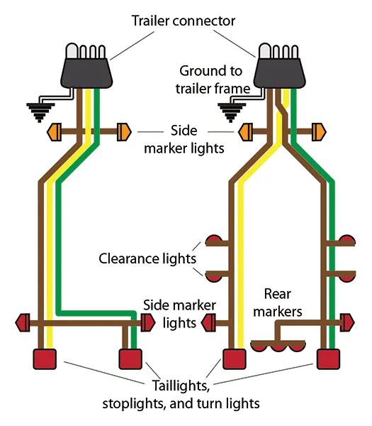
A 4 pin trailer wiring diagram guide shows four connections: ground (white), taillights (brown), left turn/brake (yellow) and right turn/brake (green). This flat connector handles basic trailer lighting for utility trailers, boat trailers and small cargo trailers under 80 inches wide.
The 4-pin flat is the most common trailer connector in North America. If your trailer only needs running lights, brake lights and turn signals—no electric brakes or auxiliary power—this is the connector you need.
4 Pin Trailer Wiring Diagram
Standard Color Code
| Pin | Wire Color | Function | Vehicle Circuit |
|---|---|---|---|
| 1 | White | Ground | Chassis ground |
| 2 | Brown | Tail/Running lights | Parking light circuit |
| 3 | Yellow | Left turn/brake | Left turn signal |
| 4 | Green | Right turn/brake | Right turn signal |
Pin Layout (Looking at Connector Face)
Vehicle Side (male pins):
┌─────────────────────┐
│ ● ● ● │
│ GRN YEL BRN │
│ ● │
│ WHT │
└─────────────────────┘
The ground pin (white) sits offset from the three signal pins. This prevents incorrect insertion and ensures ground connects first when plugging in.
Connector Types
4 Way Flat (Most Common)
The standard rectangular connector found on most light-duty trailers.
Specs:
- Amperage: 5-10 amps per circuit
- Wire gauge: 16-18 AWG typical
- Max trailer width: 80 inches (DOT requirement for simple lighting)
Best for: Utility trailers, boat trailers, motorcycle trailers, small cargo trailers
4 Pin Round
Less common but found on some older trailers and imports.
Note: Same wiring, different connector shape. Pin positions vary by manufacturer—always test before connecting.
How to Wire
Tools Needed
- Wire strippers
- Crimping tool
- Electrical tape or heat shrink
- Test light or multimeter
- 4 pin connector (male for vehicle, female for trailer)
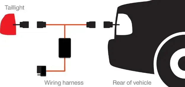
Vehicle Side Installation
Step 1: Locate tap points
Find the vehicle’s tail light harness, usually accessible behind the bumper or in the trunk/bed area. You need access to:
- Left turn signal wire
- Right turn signal wire
- Tail/running light wire
- Ground point
Step 2: Identify vehicle wires
Use a test light with someone operating the vehicle controls:
- Turn on parking lights → tail wire illuminates test light
- Activate left turn → left turn wire flashes
- Activate right turn → right turn wire flashes
Step 3: Make connections
For each connection:
- Strip 1/2” of insulation from vehicle wire
- Strip trailer harness wire
- Use butt connectors or solder and heat shrink
- Tape or loom for protection
Step 4: Ground connection
The ground is critical. Options:
- Connect to existing vehicle ground point
- Create new ground on clean, bare metal
- Sand paint away and use self-tapping screw with ring terminal
Trailer Side Installation
Step 1: Run wires
Route wires from the connector mount point to each light:
- Main harness down trailer tongue
- Split to left and right at trailer body
- Branch to each light fixture
Step 2: Protect wiring
- Use split loom or wire conduit
- Secure every 18-24 inches with zip ties
- Keep wires away from moving parts
- Allow slack at hinge points (like tailgates)
Step 3: Connect lights
Most trailer lights have:
- White wire = ground
- Color-coded wire = function (matches harness)
Ground each light to the trailer frame with a dedicated ground wire. Don’t rely on mounting screws for ground—this is where most problems start.
Step 4: Final ground
Run the main white ground wire to bare metal on the trailer tongue. This connects through the coupler to the tow vehicle. Add a dedicated ground wire running back to the vehicle for reliability.
Troubleshooting Problems
Lights Don’t Work At All
Check in order:
- Fuse at tow vehicle (usually in fuse box, labeled “trailer”)
- Ground connection at vehicle side
- Ground connection at trailer side
- Connector contact corrosion
One Side Doesn’t Work
Likely causes:
- Bad bulb on that side
- Broken wire in harness
- Corroded connector pin
- Bad ground at that specific light
Test method: Use test light at connector. If power present at connector but light doesn’t work, problem is trailer-side.
Lights Work But Are Dim
Causes:
- Poor ground (most common)
- Corroded connections
- Undersized wire (voltage drop over distance)
- Multiple lights on single circuit overloading
Fix: Improve grounds. Run dedicated ground wire from each light cluster to trailer frame, and from trailer frame to vehicle frame.
Turn Signals Flash Fast or Slow
Fast flash: Low resistance detected. Usually a burned-out bulb or bad connection on trailer.
Slow flash: High resistance. Corroded connector, poor ground, or undersized wires.
Vehicle Lights Affected When Trailer Connected
Cause: Ground loop or short between trailer and vehicle circuits.
Fix: Ensure trailer lights are completely isolated from trailer frame if lights have internal grounds. Better: use a trailer light converter/isolator if vehicle uses combined brake/turn circuits.
Adapter Options
4 Pin to 7 Pin Adapter
Allows connecting a 4-pin trailer to a vehicle with 7-pin connector. Common when tow vehicle has 7-pin for travel trailer but you’re pulling a utility trailer.
Limitations: Only basic lights work. No electric brakes, no 12V power, no reverse lights through adapter.
7 Way to 4 Way Adapter
Allows connecting a 7-pin equipped vehicle to a 4-pin trailer—basically gives you only the functions the 4-pin trailer can use.
Note: Electric brake output from vehicle has nowhere to go. Not a problem, just unused.
Wiring Tips for Reliability
Use Quality Connectors
Cheap connectors corrode faster. Look for:
- Sealed/weatherproof designs
- Brass or tin-plated contacts
- Strain relief at wire entry
Seal All Connections
Water is the enemy. Use:
- Adhesive-lined heat shrink
- Dielectric grease inside connector
- Weatherproof junction boxes
Size Wire Correctly
For runs over 20 feet, step up wire gauge:
- Under 20 ft: 18 AWG OK
- 20-35 ft: 16 AWG
- Over 35 ft: 14 AWG
Add a Ground Strap
Run a separate ground wire from trailer frame to vehicle frame. The ball/coupler connection corrodes and adds resistance.
Test Regularly
Before each trip:
- Connect trailer
- Turn on running lights—verify all lit
- Check left turn
- Check right turn
- Check brake lights
Takes 30 seconds and prevents getting pulled over.
When to Upgrade from 4 Pin
Consider moving to a larger connector if you need:
| Need | Connector Required |
|---|---|
| Electric trailer brakes | 5-pin or 7-pin |
| 12V auxiliary power | 6-pin or 7-pin |
| Reverse/backup lights | 6-pin or 7-pin |
| Trailer over 80” wide | May require separate marker lights on different circuit |
Related Guides
- 5 Pin Trailer Connector — Adding electric brakes
- 6 Pin Trailer Connector — Round connector with aux power
- 7 Pin Trailer Connector — Full-feature heavy duty
- Trailer Wiring Diagram Guide — All connector types compared
- Automotive Circuit Tester — Testing trailer circuits